Road cross sections
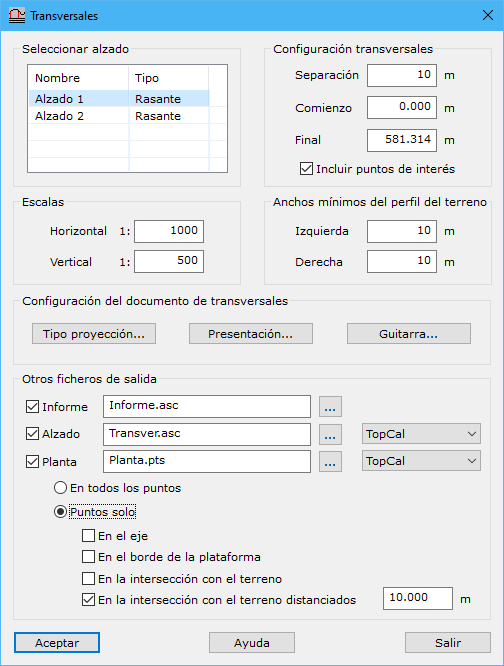
This tool calculates road cross sections and generates a new drawing document using these settings:
- Select vertical alignment: vertical alignment used to apply the horizontal alignment's associated template cross sections.
- Cross sections settings
- Interval: spacing along the alignment between cross sections, in meters.
- Start: starting chainage in meters, default 0.
- End: ending chainage in meters, default total alignment length.
- Scales: horizontal and vertical scale denominators, determining vertical exaggeration and geometric limits for filtering unnecessary profile definition points.
- Offsets: minimum widths in meters of the terrain profile obtained from the DTM, measured from the road axis. Regardless of road width, all road profiles have at least these widths.
Configure vertical alignment projection onto the DTM with Type of projection.
Change cross-section arrangement through Presentation.
Change information displayed below cross sections through Annotations.
The new drawing document can be saved as DIGI BIN, AutoCad DXF or AutoCad DGN. Additional documents can include:
- Report of each profile's cut and fill areas.
- Vertical view of each cross section's points, in TopCal, Clip, Genius or TCP MDT format for use in those programs.
- Plan view of each cross section's points, useful for setting out, in TopCal or ASCII. Choose points to include:
- At all points: every cross-section change of direction.
- Only at:
- At the axis: central cross-section point.
- At the edge of the platform: profile platform endpoints.
- At the intersection with the ground: template-to-terrain intersection.
- At the intersection with the ground apart: points at a specified offset from the template-to-terrain intersection.