Road profile annotations
This dialog configures the frame containing a longitudinal profile and its additional information.
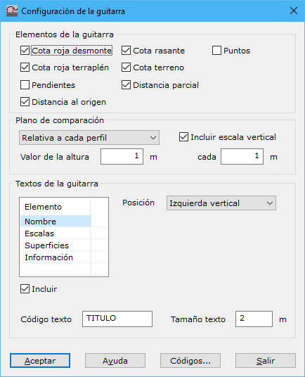
At the top, select elements for the lower frame's data bands. Fields are filled automatically from calculated profiles:
- Cut/fill depth: difference between design and ground elevations. Design below ground represents cut; otherwise, fill.
- Design/ground elevation: design grade or digital terrain model elevation.
- Partial distance and distance from origin: distance in meters from the profile origin or last point referenced in the bands.
- Points: point type text for important alignment points: TE, curve entry tangent; TS, curve exit tangent; TEC, entry tangent to a circle between clothoids; TSC, exit tangent from a circle between clothoids; Start, alignment beginning; End, alignment end.
- Alignments: diagram of alignment elements, with different graphics for straight lines, circles and clothoids, accompanied by texts showing significant values.
For example, a circular element is shown as:

An element with a clothoid is shown as:

The position above or below indicates curve direction.
- Superelevations: diagram with two lines for left and right road superelevations. Their positions depend on superelevation signs.
Configure the frame's comparison plane and optional vertical scale:
- Plane of comparison: Absolute uses Height value directly. Relative to each profile subtracts it from each profile's lowest elevation. Relative to all profiles subtracts it from the lowest elevation across all profiles. If an absolute value lies above a calculated profile's minimum elevation, a dialog resolves the conflict.
- Height value: absolute or relative comparison plane elevation, in meters.
- Include vertical scale: horizontal lines parallel to the comparison plane showing different elevations. Set spacing in the field below.
Set the frame entity codes with Annotation code and Internal line code.
Select texts to display inside and around the frame, enabling Include below the list. Their parameters are:
- Position: location around the profile frame. Not available for Information or Vertical curves texts.
- Text code: recording code.
- Text height: height in meters.
Available texts:
- Name: profile name.
- Scales: horizontal and vertical scales from Road document information.
- Areas: calculates and displays cut and fill areas when a design grade is available.
- Information: texts for fields selected at the top, displayed as data bands below the frame, with different settings:
- Distance from origin: distance in meters from the first longitudinal profile point's origin.
- Distance from last point:
- Information: includes information at every profile change of direction, if labels do not overlap, or at a specified distance interval.
- Vertical curves: box above each parabolic vertical curve containing chainage, elevation, Kv, length and vertical offset.