Volumes
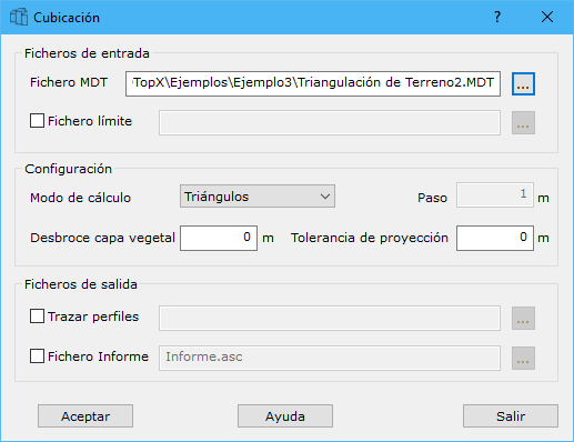
Complete these fields:
- DTM file: digital model onto which prisms are projected for volume calculation. It must overlap the current document and the boundary used. Find the file with Windows Explorer using the [...] button to the right.
- Boundary file: volume calculation boundary. Formats: DIGI BIN, AutoCad DXF, MicroStation DGN or ASCII coordinates defining the boundary. It can contain one or more closed lines; ASCII supports only one line. Find the file with Windows Explorer using the [...] button to the right.
- Calculation mode: intersect triangles or use a grid with the specified Step in meters. Triangle intersection takes longer but is more accurate. Grid calculations become more accurate with a smaller step and faster with a larger one.
- Topsoil stripping: terrain topsoil thickness in meters. Before comparing models, the program removes this layer's volume from the original model because it should not count toward cut or fill.
- Projection tolerance: elevation difference in meters below which projected points on the DTMs are considered equivalent. For example, with 0.5 m, projected differences below that amount are treated as zero. DTMs may come from mapping with a given production tolerance, making smaller differences unsuitable for interpretation as cut or fill.
- Draw profiles: projects profiles onto the resulting volume model, displaying two lines projected onto the two digital models. Use the [...] button to configure profiles.
- Report file: ASCII file listing calculated volumes. Use the [...] button to select its location in Windows Explorer.
Requires an active triangulated digital model document.