Cross sections
This dialog has three tabs:
- Geometry
- Graphic presentation
- Output files
Geometry
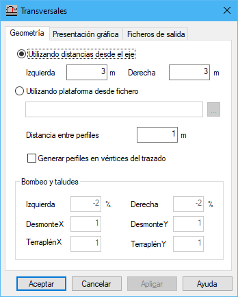
Complete these fields:
- Width:
- Using distances from the axis: design width to the left and right of the axis, in meters.
- Using platform from file
- Distance between profiles: distance between consecutive cross sections, in meters.
- Generate profiles at alignment vertices
- Crossfalls: design crossfall percentages to the left and right, measured from the axis.
- Slopes: X-to-Y displacement ratio for calculating intersections between the design grade and terrain, separately for cut and fill.
Graphic presentation
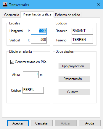
Complete these fields:
- Scales: vertical and horizontal scale denominators for profiles recorded in the drawing file.
- Codes: codes for lines representing the design grade and terrain.
- Plan drawing: elements in the road plan document.
- Generate chainage texts: labels each cross section with its chainage.
- Height: text height in meters.
- Code: code for recording texts.
- Other settings:
Output files
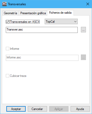
Complete these fields:
- ASCII output file: cross-section output file, with points expressed as distances from the origin and elevations.
- ASCII file type: output format: TopCal, Clip or Genius.
- Output report file: ASCII report of generated cross sections.
- Calculate alignment volume: calculates volume between the proposed alignment and the original terrain.