Contours
Complete these fields:
- Scale: final document scale denominator, needed to determine precision when smoothing and generalizing contours.
- Smooth and generalize on breaklines cuts: enable when exact contour intersections with breaklines are unimportant. At some large scales, contours must not be generalized or smoothed where they cross breaklines such as roads or paths, so disable this option.
- Advance Settings...: opens a dialog with advanced contour options, including generalization.
- Set up codes...: opens a dialog specifying codes for different entities.
- Respect registered contour lines with codes: uses contours included among the digital terrain model's breaklines when generating new contours. Existing contour paths take precedence during calculation. Specify minor and/or index contour codes; leave an unknown code blank. The existing contour interval need not match the new one.
- Use height limits: generates contours only within a specified elevation range. The program displays the digital terrain model's elevation range to help you choose.
- Interval: vertical spacing in meters between contours. The index contour interval must be a multiple of the minor contour interval, usually four or five times larger.
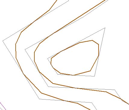
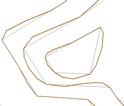
- Smoothing: contours interpolated within individual triangles and joined together can be smoothed. Two algorithms are available, with optional checks for intersections between smoothed contours:
- Type: no smoothing, B-splines or cubic splines. Without smoothing, directly interpolated contours have angular shapes. B-splines generate curves tangent to the different segments without passing through their vertices. Cubic splines generate smooth curves passing through every original contour vertex.
- Factor: choosing smoothing enables a control to the right for setting the smoothing factor from 10, maximum, to 1, minimum. It weights how closely the curve follows the original unsmoothed line. For cubic splines, 10 corresponds to natural cubic splines.
- Smoothing factor: joined contours interpolated within individual triangles can be smoothed using cubic splines. Natural cubic splines give maximum smoothing at 10. Values from 1 to 9 use weighted cubic splines, with increasing smoothing.
- Check cuts between contour lines: excessive smoothing can distort results and cause nearby contours to intersect. The program detects and fixes these errors, but this may unnecessarily lengthen calculations where contours are far apart, so the step can be disabled.
- Limit file: drawing file defining the contouring area. Formats: DIGI BIN, AutoCad DXF, MicroStation DGN or ASCII coordinates defining the boundary. The boundary can contain one or more closed lines; ASCII supports only one line.
- Set height figures in index contours: records elevation labels along index contours. Labels use these parameters:
- Separation: spacing in meters between texts on the same contour, measured along it.
- Text height: label height in meters.
- Decimals: number of decimal digits in contour elevation labels.
- Gap in contour lines: leaves gaps in labeled contours where text is placed.
Requires an active triangulated digital model document.
Example
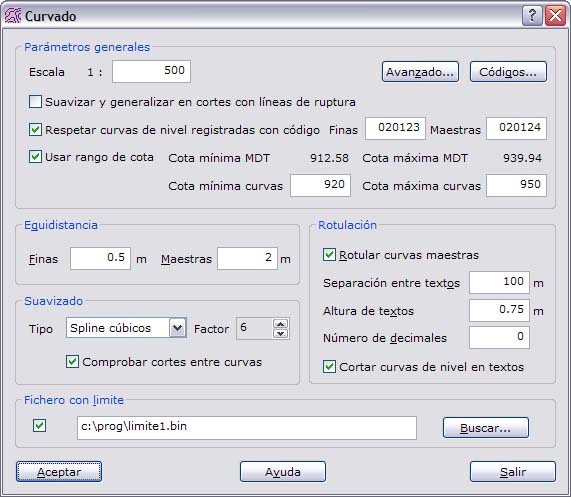
This example generates contours at scale 500, using cubic spline smoothing at level 6, a moderate setting, with minor contour intervals of 0.5 meters and index intervals of 2 meters. Contours are not smoothed where they cross breaklines, and existing model contours with codes 020123 and 020124 are respected. Index contours are labeled with text spaced 100 meters apart, 0.75 meters high and without decimal places; gaps are left for labels. A boundary file restricts contouring to its interior, and only elevations from 920 to 950 meters are contoured.